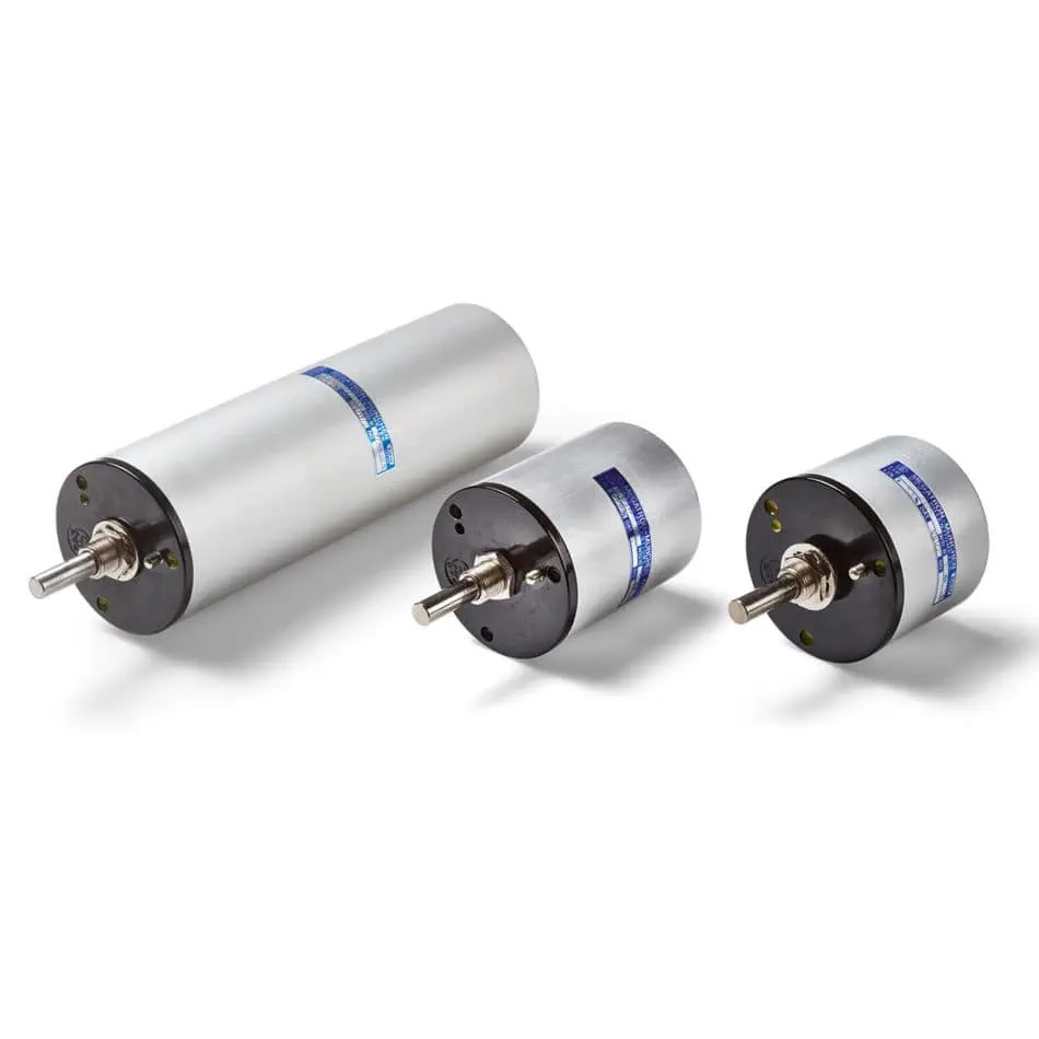
The electrical and electronic component is the general term for the different parts of an electrical circuit. These components are used to build the circuit. These components are categorised as active components and passive components. The components that supply and control the energy are called the active components. The components that respond to the flow of energy and can store or dissipate energy are called the passive components. The capacitor is a passive component.
Capacitor
The capacitor is a passive component that stores energy, and it has two capacitor plates with a dielectric between them. The charge capacity of the capacitor is increased using a dielectric. The dielectric can be air, glass, paper, mica, ceramic etc. The capacitor will store energy when the charge is forced onto the terminals of the capacitor from a power source. The charge is stored in the capacitor even after the power source is disconnected. The capacitor is used along with a resistor in a timing circuit. The capacitor acts as a filter by blocking the DC signal and allowing the AC signal to pass. The charge stored in a capacitor is given by,
Q = CV
Here, C is the capacitive reactance
V is the applied voltage
Capacitor in Series
Several capacitors can be connected in different ways. Multiple capacitors, when connected, act as a single equivalent capacitor. The equivalent capacitance depends on the individual capacitors and the way it is connected. The capacitors are generally connected in series and in parallel. The capacitors in series combination has a capacitance less than the individual capacitors. The total value of the capacitor connected in series is equal to the sum of the reciprocal of the individual capacitance of each capacitor connected in series. If C1, C2, C3 —–Cn are the capacitance of the capacitors connected in series, the equivalent capacitance of the series combination of capacitors is given as,
1/Cequ = (1/C1) + (1/C2) + (1/C3) ——(1/Cn)
The voltage across the capacitors is V1, V2,V3 ——-Vn, respectively. Therefore, the effective voltage,
V = V1 + V2 + V3 ——Vn
Potentiometer
The potentiometer is actually a long wire connected across a standard cell. In the actual design, the long wire is cut into several pieces, and it is placed side by side, and it is connected at the ends with a metal strip. A rheostat is connected to the potentiometer to change the resistance manually. By varying the resistance manually, the potential difference between the two points can be calculated. The potentiometer is an instrument used to measure the unknown voltage by measuring the known voltage.
The principle of the potentiometer is that the potential drop across any part of the wire is directly proportional to the length of the wire, provided the wire is of a uniform area, and a uniform current flows through it. The sensitivity of the potentiometer is the smallest change in the potential difference that can be measured by a potentiometer. The potential gradient is decreased by increasing the sensitivity of the potentiometer.


